Connections Summary
Connections Summary - see the descriptions below the figure for each numbered connection.
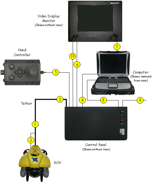
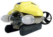
- The male tether connector on the ROV is connected to the female connector on the tether.
- The ROV strain relief cable is connected to the strain relief webbing on the tether.
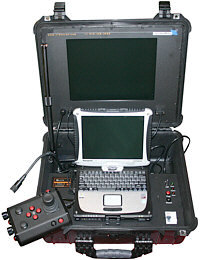
- The male tether connector is connected to the female tether connector on the control panel.
- The USB connection on the computer is connected to the USB PC connection on the control panel using the supplied USB cable.
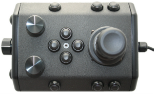
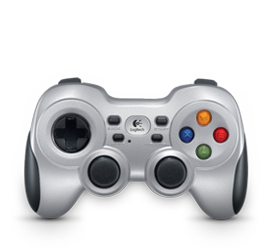
- The hand controller is connected to one of the USB ports on the computer or control panel.
- The male monitor power connector on the monitor is connected to the female monitor power connector on the control panel.
- The female VGA Out connector on the computer is connected to the female VGA In connector on the monitor using the supplied VGA cable.
- The computer power cord is connected from the computer power cord receptacle to one of the GFCI protected IEC outlets on the control panel using the supplied country specific adapter cable.
- The control panel power cord is connected from the control panel IEC power cord receptacle to a suitable power source (100-240 Volts AC, 50, 60 Hz) using the supplied country specific power cord.
- The Analog Video Out connector on the control panel can be connected to the optional monitor's Analog Video In connector or another video display using the supplied cable. Newer control panels use a female BNC connector and include a BNC to female RCA adapter. Older control panels use only a female RCA connector. Some monitor models may have a permanently attached RCA composite male cable, or may not have this connection at all. If this cable is not used, do not leave it connected to only one side. This could result in poor video quality.
|