Pre-Dive Preparations
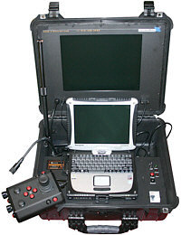
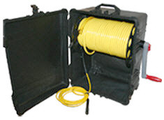
 Select a safe and preferably level area to set up the control panel. See the On-site Operations section of the Project Management Guide for more information about site selection and set up. Select a safe and preferably level area to set up the control panel. See the On-site Operations section of the Project Management Guide for more information about site selection and set up.
The pre-dive preparations consist of three parts, a visual inspection before setting up the system, setting up the system including making connections, and power on tests of the system's safety circuits and primary functions.
VideoRay Cockpit includes an online interactive Pre-Dive checklist. See the Pre-Dive Checklist section of the VideoRay Cockpit Guide
Conduct a Visual Inspection
Assuming this is your first time using the VideoRay, everything should be in proper working order and ready to go, but it is good practice to perform a pre-dive inspection before every dive, even your first. If any problems are noticed, they should be addressed before continuing. Refer to the Diagnostics and Repair section of the Maintenance Guide and take appropriate corrective action, or contact VideoRay for assistance before commencing the dive.
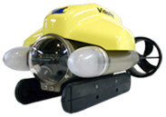
- Inspect the ROV and other system components to make sure there are no visible signs of damage or loose or worn parts. Also check for water inside the ROV hull by holding it with the front facing downward and look for signs of water in the main dome or light domes.
- Check the horizontal thrusters to make sure that the shafts are not bent and the propellers are free to spin and are not fouled, loose or binding on the thruster guards. Check the thruster cartridge seals - they are filled with oil and there should be no signs of leaking or contamination. A small air bubble in a thruster cartridge seal is acceptable. See the Maintenance Guide for warnings, replacement criteria, examples and replacement procedures.
- Check the vertical thruster to make sure the shaft is not bent and the propeller is not fouled or loose or binding on the float block. Also, check the thruster cartridge seal following the same guidelines used to check the horizontal thruster cartridge seals. Make sure the accessory port at the rear of the ROV is sealed with either a connector from an attached accessory or an accessory port terminator plug. Removal of the float block by loosening the retaining screw may facilitate this process.
Make the Connections
 Connecting or disconnecting cables while the system is powered on is not recommended. Connecting or disconnecting cables while the system is powered on is not recommended.
Most of the cables have been connected at the factory. See the appropriate sections of the Equipment Guide for detailed information about each of the connections.
You will typically need to connect only the hand controller, tether, strain relief and power cord.
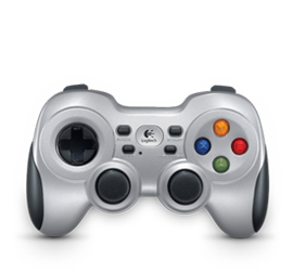
- Connect the hand controller to one of the USB ports on the control panel or directly to one of the USB ports on the computer.
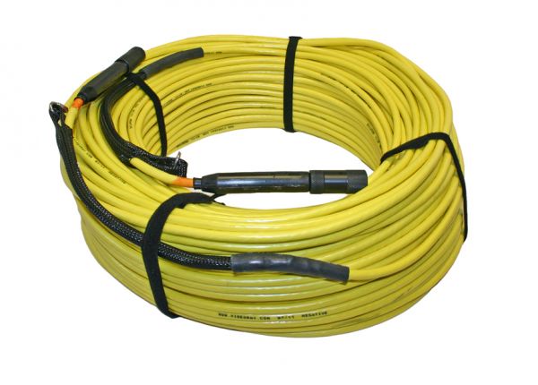
- Connect the female end of the tether connector to the ROV. The connectors have one pin that is offset towards the center of the connector. Make sure the connectors are clean, align the pins, and push the connectors together - do not twist the connectors. Secure the locking collar by screwing the halves together, and connect the strain relief cable from the ROV to the braided strap on the tether.
- Connect the male end of the tether to the control panel. When not in use, keep the tether connectors clean and protected for the best performance and reliability.
- Plug the control panel power cord into a conventional power source (100-240 Volts AC, 50,60 Hz). Power can be supplied through a land-based power outlet, generator or battery and inverter. See the Control Panel section of the Equipment Guide for power source requirements.
Power On Tests
 If the system does not pass any of the following tests, it should not be used until the problem is identified and corrected. See the Diagnostics and Repair section of the Maintenance Guide for more information. If the system does not pass any of the following tests, it should not be used until the problem is identified and corrected. See the Diagnostics and Repair section of the Maintenance Guide for more information.
The VideoRay Pro 4 includes two circuit safety components.
- The GFCI (Ground Fault Circuit Interrupter) / Circuit Breaker
- LIM (Line Insulation Monitor) Test and Reset buttons can be found on the front right side of the control panel.
Testing the Circuit Safety Components
Test the GFCI / Circuit Breaker switch (The system must be connected to a working power source to perform this test.)
IP65 Control Panel
- Press the GFCI Reset button to turn on the GFCI. The green LED should illuminate.
- Press the test switch on the GFCI. The GFCI should interrupt power and the green LED should go out.
- Press the GFCI Reset button.
Standard Control Panel
- Set the GFCI / Circuit Breaker switch to the On position.
- Press the test switch on the GFCI. The GFCI / Circuit Breaker switch interrupt power.
- Set the GFCI / Circuit Breaker switch to the On position.
Set the Power switch to the On position. The green Power On indicator light should turn on. If the green Power On indicator light is not on, make sure the system is connected to a working power source and the GFCI / Circuit Breaker switch is turned on.
Test the Line Insulation Monitor (GFCI / Circuit Breaker switch and Power switch must both be set to On in order to perform this test.)
- The yellow Alarm light should be off. If the yellow light is on, press and hold the black Reset button until the yellow Alarm light turns off.
- To test the LIM, press and hold the red Test button until the yellow Alarm light turns on. This may take up to 10 seconds. Release the button when the yellow Alarm light turns on.
- Press and hold the black Reset button to reset the LIM. The yellow Alarm light should turn off. Release the button when the yellow Alarm light turns off.
Starting the VideoRay Cockpit Control Software
Make sure the system is connected to a working power source and the GFCI / Circuit Breaker and Power switches are turned on. Start the control software.
- Turn on the computer and wait for the system to complete the boot up process.
- After the computer has started, start VideoRay Cockpit using the desktop icon, or by selecting it from the Start->All Programs->VideoRay menu.
- When VideoRay Cockpit starts, you will see the Video Window
 , the Control Instruments and the Control Bar . For now, you will only need to focus on the video window. See the VideoRay Cockpit Guide for details about using VideoRay Cockpit. , the Control Instruments and the Control Bar . For now, you will only need to focus on the video window. See the VideoRay Cockpit Guide for details about using VideoRay Cockpit.
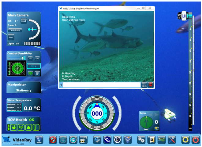
VideoRay Cockpit screen with simulated video image - your image will likely be different.
Testing the System's Functions
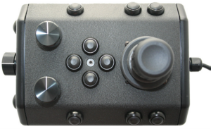
The next step is to ensure that the essential features of the ROV are functioning properly. Use the hand controller to perform the following tests. See the Hand Controller section of the Equipment Guide for more information about using the hand controller.
Test the thrusters
For the next two steps, do not operate horizontal thrusters out of water for more than 30 seconds to avoid overheating or premature wear of the cartridge seals.
- Gently move the joystick forward and backward and left and right - the horizontal thruster motors should turn the propellers. Release the joystick - it will return to center on its own, and the propellers will stop turning.
- Rotate the Depth Control knob - the vertical thruster motor should turn the propeller. Return the Depth Control knob to center to cease the vertical propeller rotation.
Test the lights
For the next two steps, do not leave the lights on bright for more than 30 seconds while the ROV is out of water to avoid overheating.
- Press and hold the Lights Bright button to increase the intensity of the lights - the lights should get brighter.
- Press and hold the Lights Dim button to dim the lights - the lights should dim.
Test the camera functions
- Press and hold the Camera Tilt Up button - the camera should tilt up smoothly through its entire range.
- Press and hold the Camera Tilt Down button - the camera should tilt down smoothly through its entire range.
- Press and hold the Camera Focus In button - the camera should focus in smoothly through its entire range.
- Press and hold the Camera Focus Out button - the camera should focus out smoothly through its entire range.
 If a manipulator or other accessories are attached, these items should be checked at this time. If a manipulator or other accessories are attached, these items should be checked at this time.
|