|
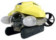
Pro 4 ArchitectureThe VideoRay Pro 4 represents a significant evolutionary, if not revolutionary, step in the development and capabilities of submersible Remotely Operated Vehicles (ROVs). Built upon a solid platform that was developed in the mid-1980s and which can now be found in service in more ROVs around the world more than any other system, the Pro 4 capitalizes on the features that have withstood the tests of time and adds the latest technological breakthroughs. Pro 3 BackgroundThe system architecture of the VideoRay Pro 3 consists of a proprietary controller (with hand controls, CPU board and power supply) on the top-side, the ROV (which also incorporates an onboard CPU) and an umbilical that connects the two. The CPUs are dated and the communications protocol between the topside and ROV relies upon CAN bus technology that became popular in the automotive industry in the early 1980s. While these systems continue to provide reliable operation, further extensibility and integration with new systems are limited. An RS-232 interface in the Pro 3's top-side CPU board allows an external computer to communicate control inputs, which in turn are relayed from the topside CPU to the ROV. This enables the ability to use COTS hand controllers, and add a few graphic features to the interface, but provides little more in terms of added features and functionality, and certainly doesn't exploit any of the true potential of today's modern CPU performance.
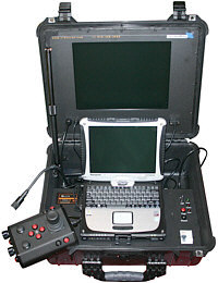
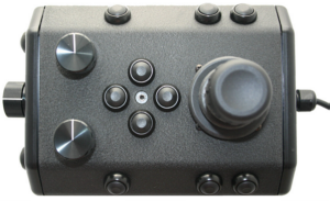
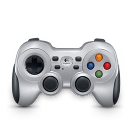
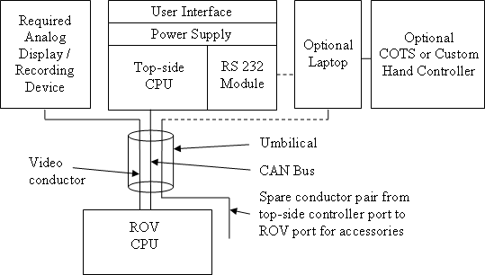
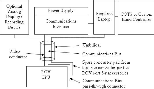
Pro 3 Functional Schematic Pro 4 Control and CommunicationsIn the Pro 4, this architecture has been overhauled and optimized. The new architecture is built around a new state-of-the-art high performance ROV CPU board and a more robust and extensible communications bus. The topside proprietary CPU board and dedicated user interface is eliminated, being replaced by a traditional high performance commercially available rugged computer and COTS or custom controllers.
Pro 4 Functional Schematic This new arrangement affords direct communications from the topside computer to the ROV CPU. In practical terms, this means that the intensive processing requirements for sophisticated features like auto depth and dive control modes can be managed locally within the ROV instead of having to communicate with the topside. Additionally, by having the topside PC communicate directly with the ROV instead of just simulating operator inputs as it does in the Pro 3, the full power of today's most advanced dual and quad core processors can be exploited. High-level programming applications will augment or completely replace the current PC Pilot software and enable the creation of unprecedented control and integration opportunities. Examples include autonomous and semi-autonomous behaviors and integration with accessory devices. One specific example might be the use of a sonar application to take over piloting the ROV to guide it directly to the location of a target signature selected by the operator (or even selected automatically through image processing and recognition analysis). Without getting too far off track, other applications might include having the ROV automatically deploy packages or take samples when it crosses programmed depth thresholds, or follow search patterns automatically. Within the Pro 3, both the topside and ROV CPUs rely on EEPROM chips to store their control software. There is no easy way to update these in the field. For the Pro 4, VideoRay will develop and deliver a Software Developers Kit (SDK). The SDK will include high-level routines that can be used as building blocks for rapid prototyping and development of new applications. The SDK will also include a module to upgrade the embedded code in the ROV. Users will be able to keep their Pro 4 up-to-date with the latest versions of control code and add new features as they become available. The VideoRay Pro 4 will not only be the best ROV platform today, but well into the future. Pro 4 Communications and Accessory SupportIn the Pro 3, a single accessory that requires a data path to the surface will monopolize the APIC (Auxiliary Pair of Independent Conductors) in the tether. This limits the number of devices that can be operated simultaneously and there is typically no coordination of the accessory data with the ROV operating parameters. While the APIC remains available in the Pro 4, additional capabilities are created by using a more universal and robust RS-485 communications protocol. This RS-485 subsystem replaces the CAN Bus used in the Pro 3. It is also made available externally on the ROV accessory port, which enables addressable multiplexing of the ROV and accessory devices. Comparison of VideoRay Pro 3 versus VideoRay Pro 4 Accessory Port
The external RS-485 connection makes possible unprecedented multiplexing and inter-communications of the ROV, accessories and/or sensor devices. Examples of the immediate possibilities include:
Extended future possibilities include:
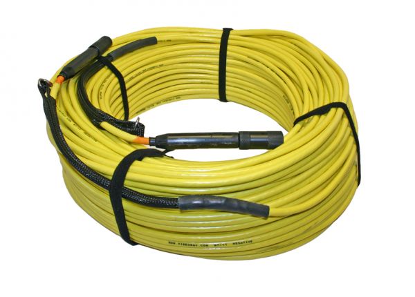
The first integrated accessory, available for immediate delivery with the Pro 4, is the KCF Technologies Smart Tether, which uses the same RS-485 communications bus. The ROV's Compass/NAV node (see below for more information) also serves as the ROV node for the Smart Tether further illustrating the tight integration made possible by adopting the RS-485 protocol. Additional benefits of using the RS-485 protocol over the CAN bus are that the maximum tether length has been extended from about 360 meters (1,200 feet) to more than 600 meters (2,000 feet), and the ability to integrate new accessories is virtually limitless. Pro 4 Modular ComponentsVideoRay ROV architecture is moving in the direction of increased reliance on software to support long term implementation of features, and hardware modularity to support the diverse nature of the capability requirements based on the variety of user applications. This plan begins with the Pro 4, and will continue through future evolutions. SummaryThe Pro 4 has taken the highly acclaimed and extremely reliable Pro 3 GTO to new levels of performance by overhauling and updating many of the key components while maintaining the basic structure and form factor of VideoRay ROVs. The new system architecture also allows a continuous stream of improvements from VideoRay and as new accessories and features are added and as the SDK is put to use by accessory vendors and research institutions. |
||||||||||||||||||||||||||||||
|
|