Connecting Your Device
Device Connection
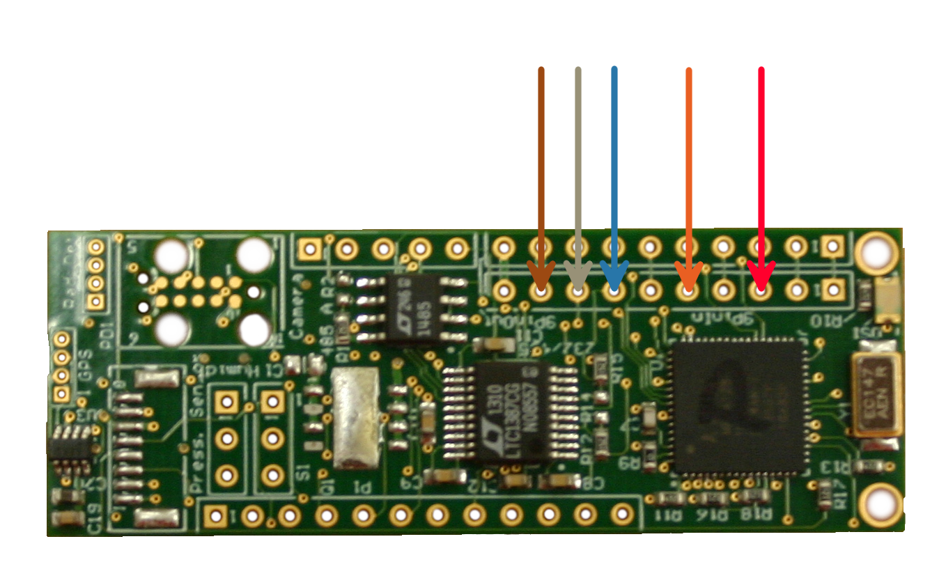
| Pin |
Arrow Color |
Function |
| 3 |
Red |
24V DC + (30 Watts) |
| 5 |
Orange |
Power Common (Ground) |
| 7 |
Blue |
RS-485+ OR RS-232 TX |
| 8 |
Grey |
RS-485- OR RS-232 RX |
| 9 |
Brown |
12V DC + (30 Watts) |
The PAM board uses the row of pins
under the PinOUT set for the connection to serial devices. This is the PinIN side of the board. The following steps will successfully connect your device:
- Identify which wires on your device are communications, power, and ground.
- Connect your device's ground wire to pin 5.
- Connect your device's communications pins.
- If you are using an RS485 device, the connection order is reversed on this side. Connect your device's RS485+ wire to pin 7. Connect your device's
RS485- wire to pin 8.
- If you are using an RS232 device, connect the TX wire of your device to pin 7. Connect the RX wire to pin 8.
- Connect your device's power.
- If you are connecting a 12V device, connect your power wire to pin 9.
- If you are connecting a 24V device, connect your power wire to pin 3.
ROV Connection
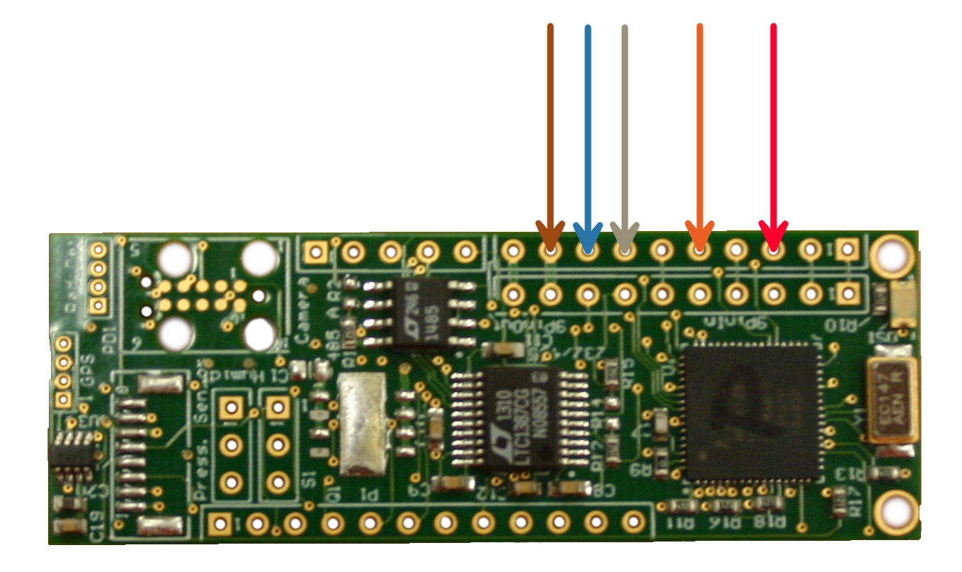
| Pin |
Arrow Color |
Function |
| 3 |
Red |
24V DC + (30 Watts) |
| 5 |
Orange |
Power Common (Ground) |
| 7 |
Grey |
RS-485- OR RS-232 RX |
| 8 |
Blue |
RS-485+ OR RS-232 TX |
| 9 |
Brown |
12V DC + (30 Watts) |
Connect the 9-pin whip to the ROV, and isolate the orange, red, gray, blue, and brown wires. Place the board with the pinOut side facing upwards. In this position, the pin numbers
for the PAM board start at 1 in the upper right and increase towards the left. The diagram above also shows the function of each pin on the board in a color coded fashion. From this position
begin soldering the wires in the following manner:
- Connect the Orange ground wire to pin 5.
- Connect the Gray RS485- wire to pin 7.
- Connect the Blue RS485+ wire to pin 8.
- Connect the Brown 12V power wire to pin 9.
- (Optional) If you are using 24V power, connect the Red 24V power wire to pin 3.
This is the typical attachment. For functions of the other wires of the whip, please see this manuals
section on the 9-pin whip.
 If your device makes use of 24V pass through power, please remember to connect the red wire to pin 3. If your device makes use of 24V pass through power, please remember to connect the red wire to pin 3.
Potting
Your device's hardware is now set up. Please remember to enclose your device in a waterproof housing before use. If you are using a permanent housing, you may wish to
test that your PAM is communicating before placing it in the housing. Proceed to the software guide to do so.
|