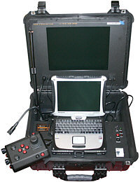
Switches and Connections
IP65 GFCI
The IP65 Control Panel uses a power cord inline GFCI. Plug the male plug of the inline GFCI into a power source and plug the Control Panel into the female socket of the Inline GFCI.
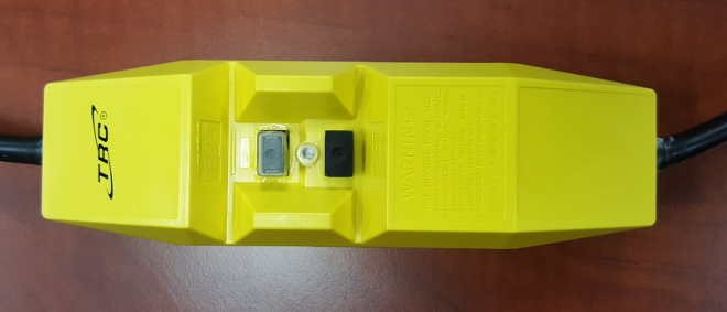
 You must turn on the GFCI by pressing the Reset button before operation. You must turn on the GFCI by pressing the Reset button before operation.
When connecting to a GFCI equipped power outlet, the inline GFCI for the IP65 control panel is not needed.
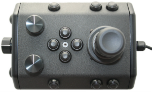
Control Panel Top
The IP65 control panel cables are twist locking connectors.
|
Connector
|
Installation
|
Removal
|
|
Power
|
Align the release tab with the rear of the panel, turn it slightly left (counter clockwise), insert the connector into its socket and then turn it back to the right (clockwise) and release the tab to secure it in place.
|
Lift up on the release tab, rotate the connector to the left (counter clockwise) and then lift the connector from its socket.
|
|
Monitor / USB / Ethernet
|
Align the pins and insert the connector into the socket. Turn the locking ring to the right (clockwise) until it clicks to secure it in place.
|
Turn the locking collar to the left (counter clockwise) and then lift the connector from its socket.
|
 The power cable and the monitor cable must be removed before closing the lid of the control panel. The power cable and the monitor cable must be removed before closing the lid of the control panel.
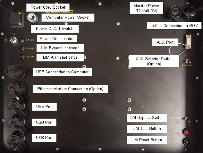
The control panel includes the following switches:
|
SWITCH
|
LOCATION
|
FUNCTION
|
|
Power
|
Control panel top
|
Turns the control panel on.
|
|
LIM Test
|
Control panel top
|
Test the LIM by simulating a fault and triggering the alarm state.
|
|
LIM Reset
|
Control panel top
|
Reset the LIM after a test or a fault has been detected and the alarm state has been triggered.
|
|
LIM Bypass
|
Control panel rear
|
If the LIM alarm state has been triggered, the LIM can be bypassed by enabling this switch.
 If the LIM bypass switch is enabled, LIM protection is disabled. This situation can pose a risk to people handling the tether or in the water with the ROV. Do not use the LIM bypass switch unless you have examined the system to make sure it is safe, or are sure that people are not going to be exposed to a possible voltage leak in the tether or ROV. If the LIM bypass switch is enabled, LIM protection is disabled. This situation can pose a risk to people handling the tether or in the water with the ROV. Do not use the LIM bypass switch unless you have examined the system to make sure it is safe, or are sure that people are not going to be exposed to a possible voltage leak in the tether or ROV.
|
|
AUX Port Selector Switch (Optional)
|
Control panel rear
|
Switches the APIC circuit between the AUX Port and a dedicated accessory interface, such as an Ethernet connector, if one is included.
|
The control panel includes the following connections:
|
CONNECTION
|
TYPE
|
FUNCTION
|
|
Power (100-240 Volts AC, 50, 60 Hz)
|
IEC male
|
Used to connect the control panel to a power source.
|
|
GFCI/Circuit Breaker Protected Power Outlets (2)
|
IEC female
|
Used to connect the computer and another device to the control panel to receive power.
|
|
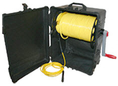
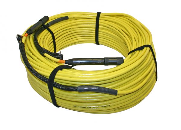
Tether Whip (Specifications)
|
8 pin round female
|
Used to connect the control panel to the tether for power, communications, video and accessory support.
|
|
Monitor Power
|
|
Provides 12 Volts DC. Used to provide power to the monitor.
|
|
Analog Video Out
|
RCA female
|
Provides a composite video signal. Can be used to connect an analog video recording device.
|
|
USB PC
|
Type B female
|
Used to connect the control panel to the computer.
|
|
USB Accessory pass through (3)
|
Type A female
|
Can be used to connect USB devices to the computer via the control panel.
|
|
AUX Port (Specifications listed below)
|
DB-9 male
|
Provides access the APIC (Auxiliary Pair of Independent Conductors) in the tether. Can be used with ROV accessories that need to rely on the APIC for communications.
|
3
|
Ethernet (Optional)
|
RJ-45 female
|
Can be used to connect the control panel to the computer for Ethernet based ROV accessories.
|
|
BlueView Pole Mount (Optional)
|
|
Used to connect the BlueView Pole Mount system to the control panel.
|
AUX Port Specifications
|
PIN
|
FUNCTION
|
|
1
|
No connection
|
|
2
|
No connection
|
|
3
|
No connection
|
|
4
|
No connection
|
|
5
|
No connection
|
|
6
|
No connection
|
|
7
|
AUX + (Connects to tether pin 4 and ROV accessory port pin 4)
|
|
8
|
AUX - (Connects to tether pin 6 and ROV accessory port pin 6)
|
|
9
|
No Connection
|
Connector Type - DB-9 Male.
The AUX Port provides access to the APIC. Some accessories use the AUX port directly and the topside device requires a female DB-9 connector. Some accessory interfaces can be built into the control panel. For control panels that have built-in accessory interfaces, there is a switch on the back of the control panel that determines whether the APIC is connected to the AUX port, or to the accessory interface inside the control panel. The switch must be set to the proper position depending upon whether you want to use an external device or the built-in accessory interface. Set the switch to AUX if you want to use an external accessory device on the topside. Set the switch to the correct setting for any built-in accessory device that you want to use. For built-in accessories, there is either another dedicated connector (to connect to the laptop), or the accessory might use USB (to connect to the laptop), in which case a separate connector is not necessary. See the instructions that come with each accessory for more information.
|