|
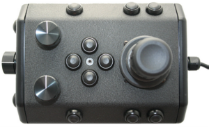
Safety CircuitsThe Control Panel includes two safety circuit components.
GFCI (Ground Fault Circuit Interrupter) / Circuit BreakerThe GFCI / Circuit Breaker protects the operator from shock from the AC circuit of the power source, and protects the equipment from a current overload. The GFCI has two operating switches and a test button. To energize the control panel, both switches need to be turned on. If the GFCI detects a differential current between the supply and ground poles of the power source, it will trip, or open the circuit. If the circuit breaker detects a current greater than it's rating, it will trip. The test button can be used to simulate these conditions and pressing and holding the test button should cause the switches to open, or turn off. If the GFCI continues to trip, the system should be inspected for a fault before being used. LIM (Line Insulation Monitor)The LIM protects the operator and persons in the water nearby from shock from the DC circuit of the tether. While the GFCI switches are part of the GFCI component and must be turned on to operate the control panel, the LIM switches are separate components and the LIM does not need to be turned on. The LIM switches include Reset and Test. When power is applied to the control panel, the LIM is active. The LIM operates on a principle similar to the GFCI and detects differential current. If the differential current exceeds a threshold, the LIM will trip. When the LIM trips, the yellow LIM Alarm LED will turn on. The LIM can be reset by pressing and holding the Reset button. The yellow LIM Alarm light should turn off. To test the LIM, press and hold the Test button. If the LIM continues to trip, the system should be inspected for a fault before being used.
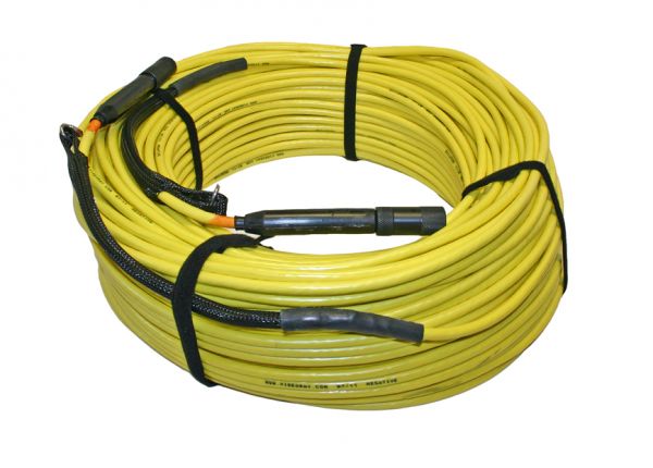
LIM BypassIn some situations, the LIM may trip, but the system may in fact be safe to use. A common situation that may cause the LIM to trip is using an old tether that has some current leak at its connectors. The LIM is sensitive enough to detect this leak. If it is determined that the cause of the LIM tripping does not represent a potential hazard to the operator or people in the surrounding area, the LIM can be bypassed to continue operations. The LIM can be bypassed by engaging the LIM Bypass switch to the Bypass setting. The LIM Bypass switch is a locking switch and the stem of the switch must be pulled out to switch it. When the LIM is set in Bypass mode, the RED LIM Bypass LED will turn on indicating the system may be unsafe to operate.
|
|
|
Pro 4 Operator's Manual